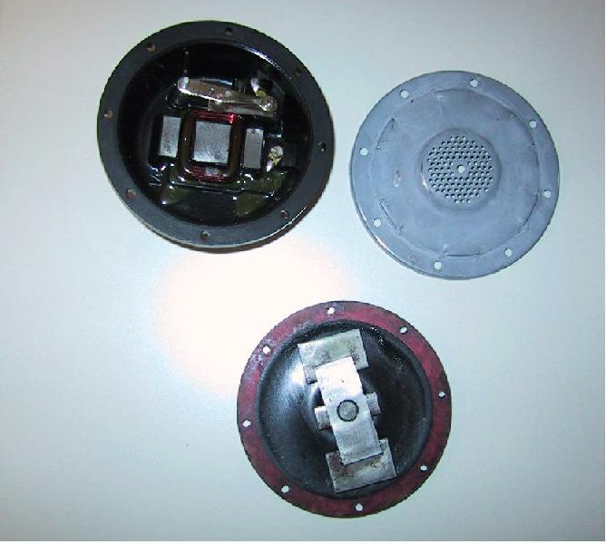
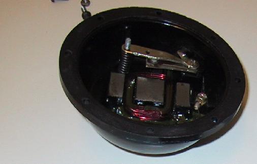
Picture 1: Horn disassembled.
Current flows in from a terminal and its screw (picture 1, top right), through the contact points (top middle), actuates electric magnet (shiny metal parts below that, inside red coil) and leaves to another terminal screw (bottom right). The coil moves the plate (separate part below body) inward, breaks the electric connection and plate returns to original position and this vibration produces quite unique, sneezy sound typical to Beetle.
Also a note on Ghia horns: It has dual-tone horns and the low tone is the standard Beetle horn, while the other has higher frequency, marked as FH.
Picture 1: Horn disassembled.
As the picture above shows, the horn has only three major parts: the body, the plate and the cover. The body consists of breaker points, adjustment screw, coil, terminals and terminal scews.
If the horn is not working properly, there are two main faults:
1) Horn is misadjusted (Spring loaded adjustment screw can be seen in pictures 4 and 5 on the left side.)
2) There is one or more oxidized connections.
The coil itself is very rugged and it's not easy to burn it. I have two 6V horns on 12V system (Ghia) and they are not only working fine but very loud, too.
Measure resistance between terminals. It should be very low, at most few ohms (mine is basically zero, ~2 ohms). If it's not(=breaker points open or burnt), then adjust the adjustment screw to clockwise until you get low resistance(=breaker points close). If you can't get it, then move to section Connections, as points are dirty or burnt.
When you have low resistance, you can test the horn: general adjustment advice is to make it as loud as you can. You could also use an ampmeter to measure the current running through, but I don't know the nominal value for it. Mine takes about 8A.
If you get no sound at this point, the breaker might be too closed and it won't open at all, so adjust the screw counterclockwise until connection breaks and then clockwise again so that connection is just made. Then you should have some noise and you could adjust it to the maximum.
There are only three joints/breaking points in horn electric circuit, so if there is much resistance, it should be easy to locate the oxidized joint. Usually the breaker points are in bad shape and need cleaning (I've two horns and in 2001 the other one was mute because of that, this time (2015) both).
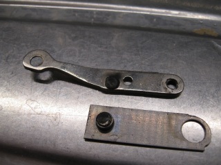 Picture 2: Current breaker points before cleaning, no current through and non-functional horn
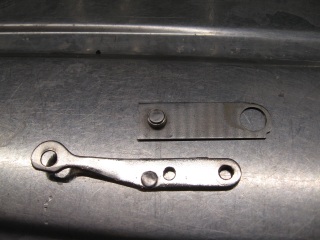 Picture 3: After sanding with 1000 grit paper on glass and polishing with Autosol. Still not perfect but it works.
Two other joints are under the screws which also holds the terminals in place (picture 4, right. The other horn was mute because of the other screw was oxidized.).
Also cleaning the terminals is a good idea if the body is disassembled. Be careful when assembling the terminals, they should have two small paper seals each, within the body and those are easily lost or broken. Also check that contact breaker and its parts are in right order, there should be no contact between upper and lower part if breaker points are open.
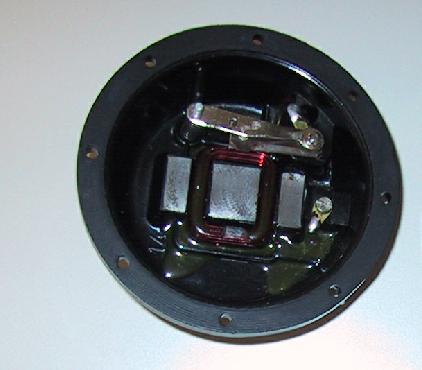 Picture 4: Horn body.
 Picture 5: Horn body, adjusting screw and coil showing.
Page created 7.1.2001/Modified 12.7.2015